Detailed steps for board replacement
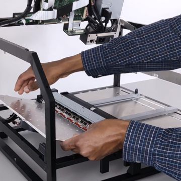
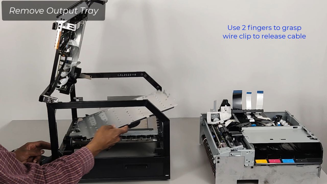
Please watch the Open/Close Printer Video to access printer boards.
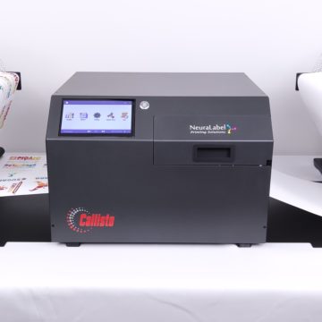
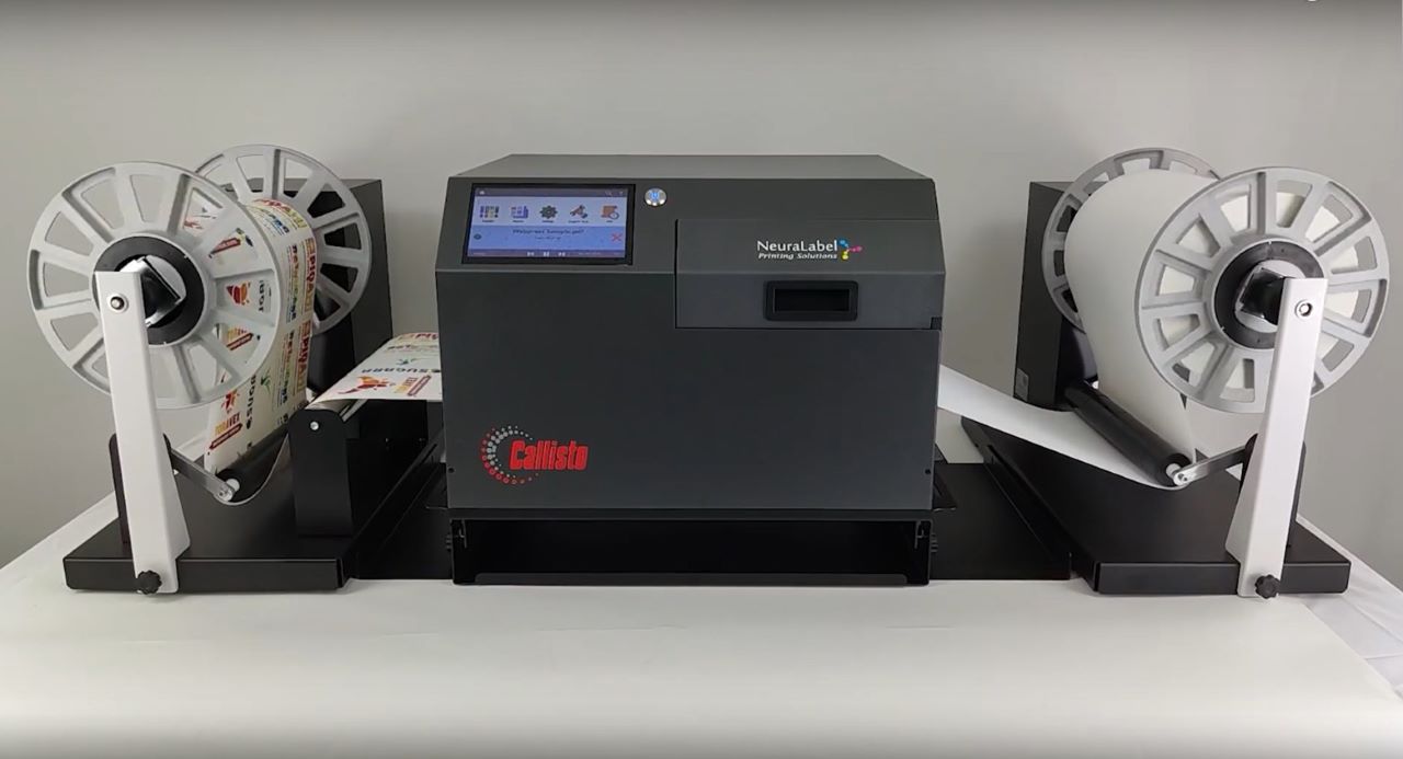
This video covers the replacement of the OEM1 and OEM 2 boards in both the Neuralog and NeuraLabel versions of the Callisto printer.
Steps Included to Replace the OEM1 OEM2 Boards
1. Remove Cables
2. Remove OEM1-OEM2 Assembly
3. Seperate OEM1 Board from OEM2 Board
4. Install new OEM2 (or OEM1) Board
5. Reattach OEM1-OEM2 Assembly
6. Reattach Cables
Cable Removal
Remove Cables in this recommended order.
- Power
- HDMI
- 2 Ethernet
- Power Button Cable
- 3 Ethernet Cables ABC, 2 Ribbon Cables (Ribbon Cables are Keyed; 11 and 19 pins)
- Ribbon Cable OEM1 to Main PCS
- USB Attached to OEM1
- Door Sensor to OEM1
OEM1 OEM2 Board Assembly Removal
Remove the OEM1 OEM2 Board Assembly from the printer.
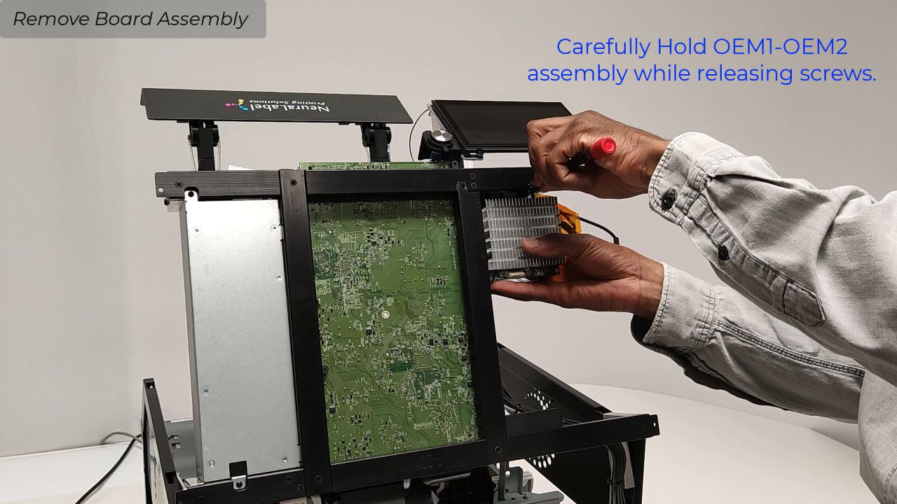
Remove 3 screws with Phillips screwdriver; older boards may have 4 screws
Carefully hold OEM1-OEM2 assembly while releasing screws.
WARNING: Do not let screws fall into the BnB (printer engine). This could damage the unit. For extra protection, cover the BnB with an anti-static cloth.
Once removed, set OEM1-OEM2 assembly aside.
OEM1 OEM2 Board Separation (if needed)
Separate the OEM1 board from OEM2 board.
In most cases an OEM1-OEM2 combo will be sent as a replacement part. If this is not the case follow these steps.
Remove Power Button Passthrough Cable from OEM2 (top) board.
Remove OEM1 to OEM2 Cable from OEM2 (top) board.
Use a 7/64 alan key to remove the 4 screws.
Do not let the heat sink from the OEM1 (lower) board.
When detached lift the upper OEM2 board off the OEM1 board.
OEM1 or OEM2 New Board Installation
Installing a new individual OEM1 or OEM2 Board on the OEM1-OEM2 set if only one board is to be replaced.
Remove new board(s) from anti-static bag.
Follow the previous steps in reverse order
Remove board(s) from anti-static bag and move the ribbon cable from the old board to the new board.
Remove the screws from the old board.
Place 2 screws on ribbon cable side of board.
Place 3rd screw on the left side of the board next to J7.
Attach the larger mounting piece to the 2 screws.
Remount the OEM2 to OEM1 using the attachment piece.
Use the alan key to loosely tighten the screws.
Use the 4th screw to attach the small connector piece (mount).
Use the screws to attach boards with both connecting pieces.
Tighten all 4 screws. Hand tighten only. Do not overtighten.
Reattach OEM1 to OEM2 black cable to OEM2 board.
Reattach Power Button Passthrough Cable to OEM2 (top) board to location labeled PC.
OEM1 OEM2 New Assembly Installation
Install the OEM1 OEM2 Assembly into the printer.
Reattach OEM1-OEM2 assembly to the printer.
Attach the top screw first. Be very careful not to let screws fall into the printer. Use an anti-static cloth to cover the BnB (printer).
Cable Reattachment
Reattach all Cables after Replacement is Complete in this recommended order.
- 3 Ethernet Cables ABC
- USB Cable to OEM1. Be very careful plugging in the USB cable. Connector is fragile.
- Power Cable
- Silver Ethernet; Gold Ethernet
- HDMI
- Power Button Cable
- Door Sensor (switch) to OEM1 Cable
- 2 Ribbon Cables. Tip: Use a sharpie to mark one cable to distinguish it from the other. Blue Backing faces the connector back.
Verify Replacement and Close Printer
The boards replacement is now complete. You are now ready to test the replacement, and if successful, close the printer.
Keywords: Controller, OEM2, OEM1, Original Equipment Manufacturer

