The following video provides instructions for replacing the MPCA Board within the printer. The printer must be powered off and open, and the BnB must be removed, to replace the output tray. Please watch those instructional videos before attempting to remove the output tray.
A Phillips screwdriver and tool to cut a tie-wrap are needed.
There are four parts to replacing the MPCA.
- Remove Electronics Tray from Printer
- Remove MPCA from Electronics Tray
- Reinstall MPCA
- Reattach Electronics Tray on to Printer
Remove Electronics Tray from Printer
Make sure the printer cover is removed and secure the Electronics Tray with the kick-stand.
Remove the 3 black cables labeled ABC. Release 2 ribbon cables.
Cut the tie wrap that holds the cables to the Electronics Tray
Remove 1 Phillips screw. Be careful not to drop screw in BnB.
Remove one black and 2 white cables to BnB. White cables can be pulled straight down. Black cable has a latch; tilt towards you and pull down.
Grasp electronics tray. Release from kick stand. Grasp at top and at bottom near power supply. Lift up and tilt and carefully place on table.
Remove MPCA from Electronics Tray
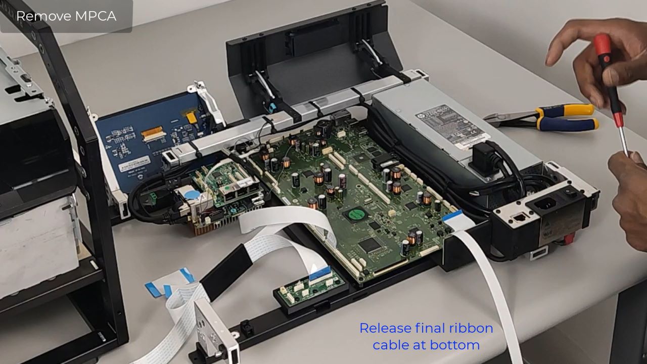
Release the ribbon cables from OEM2. Remove cables and place to the side.
Remove power cable and put to side. Release Ethernet cable. Remove USB cable that goes to OEM1. Release tie wrap holding wire bundle. Release the single wire by grasping green connector and pulling up. Release ribbon cable at the bottom.
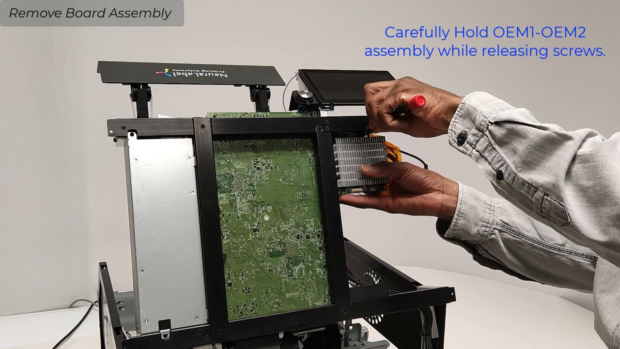
Now remove 6 Phillips head screws with standoffs. The back screw has a difficult angle but can be done. When all 6 screws are removed, the Main PCA lifts out. Once the screws are out the standoffs are no longer attached. Be careful not to lose the standoffs.
Reinstall MPCA
The new MPCA may or may not have the 2 ribbon cables already installed. Cables plug into J8 and J22.
Slide the board into place. Connect first ribbon cable before securing board into place. The line up MPCA with the standoffs and start replacing the screws. There are 2 screws that are slightly shorter; one goes directly next to the power supply; the other next to OEM2.
Do not tighten screws right away. You will need to position the board. Do not cross thread screws. Insert all screws carefully. Once board is in place, tighten all 6 screws.
Next reconnect all the cables that were removed. Reconnect simpler connectors first. Video contains detailed instructions for cable connections. Carefully tuck the wires between the connectors. Do not hit the board components (capacitors). If board components break off, the unit must be returned to the factory.
Use the supplied tie wrap to re-bundle the wires to keep them in place.
Reattach Electronics Tray on to Printer
Grab the electronics tray from the bottom (left hand) and by the power supply (right hand). Slide Electronic Tray into black clips. Put electronics tray back on its kick stand. Make sure it is secure and then reinstall the cables. Grounding cable is attached with screw. Video contains detailed instructions for cable connections.
When attaching cables make sure electronics tray is always secure either in kick stand or by holding it.
Once everything is reinstalled, release the electronics tray from its kickstand and carefully close the printer.

